CDIO rotary test rig
The rig ran at a steady 1,480–1,520 RPM on housings I designed, after I replaced a 3D-printed variable-speed gearbox that squashed under light pressure.
Group project, 4 students. My role: I designed the rig's 3D-printed housings in CAD, checked the structure with a stress simulation, and redesigned the gearbox after the first design failed.
- Output shaft speed
- 1,480–1,520 RPMmeasured
- Highest stress in the simulation
- 0.012 MPamodel
- Load on the plate: 40 g
- 0.392 N
- Tolerance on each housing
- 1 mm
The question
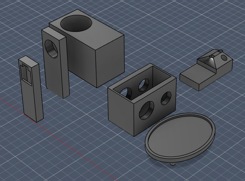
Our module asked each group of four to build a rotary test rig: a motor spins a shaft, and sensors show its speed, vibration, temperature and load live on a small screen. I shared the design and 3D-printing work. My part was the structure: every component needed a printed housing that held it at the right height on one shaft line, so nothing moved while the rig ran.
Prediction
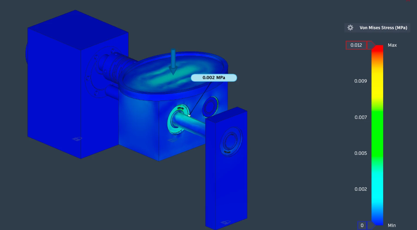
Before we ran the rig, I checked the structure with a stress simulation in Fusion (FEA, finite element analysis: the software splits each part into thousands of small pieces and works out the stress in each). I fixed the bases of the motor housing, gearbox housing and end support, and put 0.392 N on the load plate: the 40 g it would carry in testing.
The highest stress came out at 0.012 MPa, shown in the plot at the top of this page, so the structure was more than strong enough. At first the result looked as if the plate and gearbox housing had bent out of shape. They hadn't: Fusion exaggerates movement on screen so you can see which way parts bend. Once I read the scale properly, the simulation showed where stress collected, and we kept the sensors away from those spots.
Test
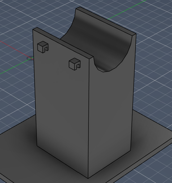
I designed each housing from calliper measurements, with 1 mm of tolerance, printed it, and changed it if it didn't fit. The motor bracket started as a half-pipe with a strap over the top. The second version encloses the motor, which slides in and is held by friction.
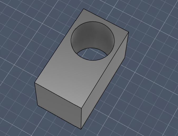
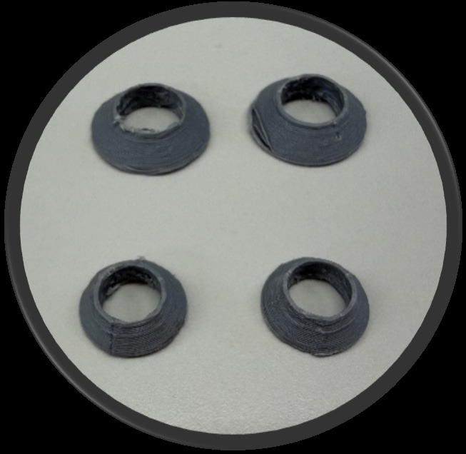
The gearbox started as a CVT, a variable-speed gearbox with a cone on each shaft that slides to change the ratio. After the first print, light pressure squashed the cones, so I dropped the CVT and redesigned the gearbox around two bought gears and a belt.
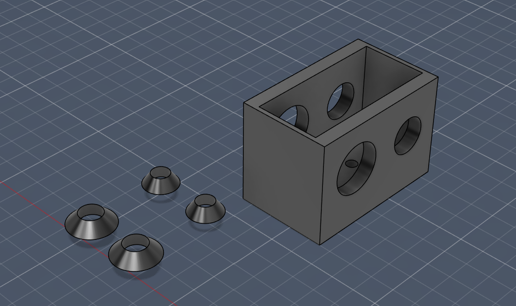
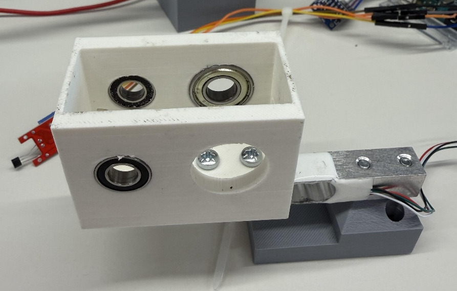
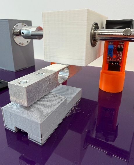
The first gearbox mount had a different problem. The load cell, the sensor that weighs the load, needs to flex slightly to measure, but the screws joining it to the gearbox held it rigid, so every test run gave errors. Moving the screw holes to the other side of the housing, under the shaft to the end bearing, fixed it.
Result
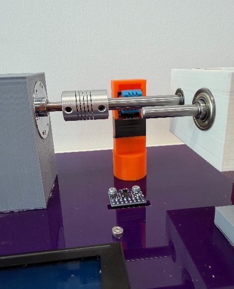
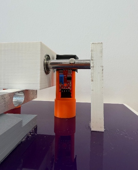
The rig ran smoothly and quietly, with no mechanical problems. The speed sensor read a steady 1,480–1,520 RPM on the output shaft: with the motor on the small gear and the output on the large one, the gearbox slowed the motor down to that.
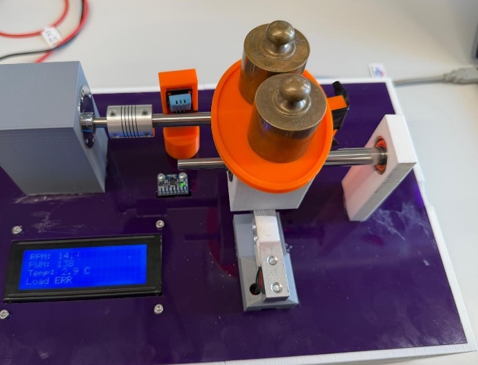
- 1Motor housing
- 2Coupling
- 3Sensor housing
- 4Weight plate
- 5Gearbox housing
- 6Load cell
- 7End-bearing support
Two sensors let us down. The temperature sensor read 7–11 °C in a room at normal temperature, so we threw its data out. The load cell read 97–98 g with nothing on the plate, then stopped working before the final tests.
The gap explained
The simulation predicted very little stress, and the structure behaved that way. But the plate only had room for two 20 g weights, so neither the simulation nor the rig ever loaded the housings hard.
The failures came from things the simulation didn't cover. The CVT cones failed because the printed plastic wasn't strong enough: light pressure squashed them before the gearbox ever ran. The load cell's 97–98 g reading was the weight of the gearbox sitting on it, which we should have zeroed out before it failed.
What I'd do next
Design the load plate to carry enough weight to really test the plastic, and run the simulation at that load, so the prediction can be properly checked. Measure each part twice before printing: several housings needed reprinting because of measuring errors. Check every sensor against a known reference before the final test, and zero the load cell with the gearbox in place.
Gallery
Revision history
No revisions. The project was complete when it was published.